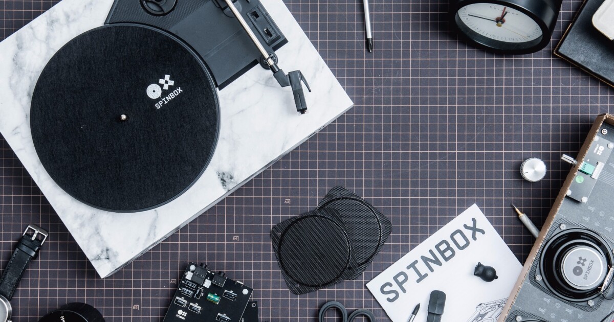
Apr 30, 2016 Find helpful customer reviews and review ratings for Make2Play D-Jay DIY Turntable Kit at Amazon.com. Read honest and unbiased product reviews from our users. This DIY turntable project was completed by Nandor Szabo, a very talented DIYer who is located in Hungary. His English is far better than my Hungarian and I agreed to assist in presenting his DIY record player project for him. I had no part in this project and am acting only like an editor. Bruce Heran. Revive sounds from a different era with this simple record player, composed of a turntable, arm with a needle and an amplifier. An educational kit for your child to build a working turntable and listen to music from another era.
I have posted a tonearm design on the AR forum of VE. It uses bearings taken from an old harddrive and components easily sourced locally. No high tech special tooling required to make this tonearm and it should be easily modified to fit other turntables. If yours does not have a sub chassis, just ignore the attachment of the shaft to the brass housing. Here are the details if anyone is interested.Click on any of the pics to get a larger image.
This is a follow up of the post “My AR77XB Mods”. One of the mods made to my TT was a new tonearm.
My criteria for all the mods are: 1. low cost; 2. use locally sourced materials, including bits found in my shed!; and 3. mod should be reversible if things do not work out.
The tonearm shown is made from the following components:
Bearings taken from a dead harddrive
A piece of carbon fiber fishing rod blank
A bit of alum. U channel
A piece off a plated brass towel rack
A piece of alum tubing and alum rod (for the “neck”)
Some heat shrink

Copper coil winding wire and some medical catheter tube
A 1in brass plumbing end cap
Some PCB sockets (to connect tonearm wires to phono leads)
gold plated PC pin sockets (to connect to back of cart)
Some bolts etc.
 An alum standard headshell purchased locally for AU$25
Essential tools were a vice, a set of threading taps/dies a drill stand and some fine drill bits.
The first thing I did was to copy the existing tonearm pivot point relative to the platter pivot point and the existing tonearm/headshell design to a drawing program on my PC and play with alternative positions and angles (pic1.) I concluded that there is no perfect size or position for the tonearm or arm pivot, but one does relate to the other. It is important to get the angle and point of stylus contact right at position A. as per standard cart alignment guides. Next I took apart my old harddrive and pulled out the bearing from the reading arm pivot and the motor and housing from the disks. (pic2). These bearings are very smooth and have NO play in them at all. The motor winding needs to be removed to get a really smooth action so you need to knock the shaft out of the center of the top bearing. Once the part with the winding is out of the bearing housing, it needs to be cut off the shaft - hacksaw adjacent to the shaft and remove from shaft carefully using pliers. Then the shaft with lower bearing can be pressed back into the housing and you now have a super smooth pivot bearing with virtually no resistance. I decided to use the smaller bearing for the vertical lift of the tonearm, as this is the firmer of the two and it has a convenient threaded hole in its housing. This firmness gives a very fluid motion to the arm. I mounted this bearing in a bit of alum U channel cut from an extrusion and mounted this assembly onto the main pivot bearing (diag3).
I used a bit of carbon fiber tube cut from a fishing rod blank for the straight arm part. The angle at the headshell was made from a bit of solid alum rod with a hole drilled through the center from each end to allow 2 medical catheter tubes containing the pairs of wires to be passed through. The commercial headshell also had a hole drilled through the center of its end and I filed off the pins as I didn’t need them. I used a short bit of alum tube and made the bayonet fitting for the headshell with two small perpendicular cuts of a hacksaw (pic4). This assembly with the wiring in place was then superglued into the narrow end of the carbon fiber tube (pic5). At the other end I used a bit of brass rod cut from an old towel rail and tapered the end to make a good fit into the tube (pic6). I cut 2 grooves into this rod to allow the catheter tubing with the wires to pass along and come out of the end of the carbon fiber tube. The tube was gently stuffed with cotton wool and then this rod was glued with araldite into the tube.
With a round file I created the right diameter notch into the tube and solid rod to seat the vertical pivot bearing at the correct pivot point along the arm. With a small hole drilled through the top I could fasten the arm to the bearing with an appropriate bolt. Remember that bearing already had a threaded hole in it (pic7).

Diy Turntable Bearing
The main pivot bearing was housed into a 1in brass plumbing fitting with an alum rod bolted to it through its base. This rod had to be offset from the center so that the whole assembly would not interfere with the arm lifter on the turntable. I also drilled and tapped 3 holes for small brass bolts that fixed the bearing housing solidly into this “cup” (pic8). This would also allow a simple VTA adjustment for the tonearm. Note that I had to sand just a little of the internal thread off the brass fitting to obtain a snug fit for the bearing housing. The rod sticking out of the base is of course to be inserted into the existing AR pivot sub chassis shaft with the plastic collar removed. To get a solid fixing I drilled and threaded a hole into said shaft underneath the sub chassis (pic9).
Diy Turntable Kit Djay For Pc
I removed the phono cables (L&R channels +&-) form the lugs, and passed them through a hole drilled into the top plate of the turntable (pic10). I wanted to make a small connector to be able to remove the tonearm with wires easily. I used a couple of PCB sockets piggybacked on top of each other mounted onto a small timber block. The whole thing looks quite neat and it has removed that risk of cutting the tonearm wires accidentally through rubbing of the subchassis on the underside of the top plate. The phono cables miss the subchassis entirely. If ever I want to change phono leads, I can easily desolder the wires from the PCB connector as it has not been glued to the timber block (pic11).Since the arm wires I used were quite stiff, I cut them short and soldered some flexible litz wire shorts from the original tonearm onto the ends. They were in turn soldered to another PCB connector.
There was only the need to modify the armlift. I drilled a very small hole into the little collar at the top and inserted modified large paperclip (see pic10). Not the most beautiful but it works very well and can be restored to the original setup if necessary.
The finished assembly works perfectly (pic12). Although this picture does not show it, the tonearm assembly does not touch the lift assembly. There is about a 2mm gap between them. I later made a new counterweight from brass with a greater mass (see pic13).
I have been extremely impressed (and surprised) with the improvement this tonearm has made to the original AR tonearm. I suspect this is due to the far superior pivot bearings; that there is not any play at all in the vertical or horizontal movement (other than the bearings of course) and the fact that there is a greater mass at the pivot point.
As well as the overall dynamics, I now have a far greater separation between bass and treble and a real improvement in the stereo sound stage. I have had no trouble with tracking at all. I even purchased a record with Bach organworks mainly to see if the deep bass would cause any problems. Result: none whatsoever.
As I am just a guy who enjoys mucking about in his shed and not an audio engineer, or have an in-depth understanding of turntable design, I am sure many of you will be able to improve on this arm.
So please don’t hesitate to make comments or suggestions on anything I’ve described.